Binome2022-10 : Différence entre versions
(→Seance 5) |
(→Seance 15) |
||
| (73 révisions intermédiaires par 2 utilisateurs non affichées) | |||
| Ligne 5 : | Ligne 5 : | ||
=<div class="mcwiki-header" style="border-radius: 40px; padding: 15px; font-weight: bold; color: #FFFFFF; text-align: center; font-size: 80%; background: #63499F; vertical-align: top; width: 98%;"> FONCTIONNALITE SUPPLEMENTAIRE </div>= | =<div class="mcwiki-header" style="border-radius: 40px; padding: 15px; font-weight: bold; color: #FFFFFF; text-align: center; font-size: 80%; background: #63499F; vertical-align: top; width: 98%;"> FONCTIONNALITE SUPPLEMENTAIRE </div>= | ||
| − | * Un clavier musical | + | * Un clavier musical + récupération de "partition" + possibilité de récupérer et renvoyer les données pour "loop". |
* 25 touches musicales, 2 touches pour changer de gamme supérieure et inférieure, 1 touche pour REC, 1 touche PLAY, 1 touche PAUSE ==> 30 Touches au total. | * 25 touches musicales, 2 touches pour changer de gamme supérieure et inférieure, 1 touche pour REC, 1 touche PLAY, 1 touche PAUSE ==> 30 Touches au total. | ||
* Retranscription des touches en sons via haut-parleur. | * Retranscription des touches en sons via haut-parleur. | ||
| − | |||
| − | |||
* LED pour le REC. | * LED pour le REC. | ||
| − | |||
| − | |||
| − | |||
| − | |||
=<div class="mcwiki-header" style="border-radius: 40px; padding: 15px; font-weight: bold; color: #FFFFFF; text-align: center; font-size: 80%; background: #63499F; vertical-align: top; width: 98%;"> LISTE DES COMPOSANTS </div>= | =<div class="mcwiki-header" style="border-radius: 40px; padding: 15px; font-weight: bold; color: #FFFFFF; text-align: center; font-size: 80%; background: #63499F; vertical-align: top; width: 98%;"> LISTE DES COMPOSANTS </div>= | ||
| Ligne 40 : | Ligne 34 : | ||
Pour le second circuit les élèves prévoient : | Pour le second circuit les élèves prévoient : | ||
* 30 touches | * 30 touches | ||
| − | |||
* 1 LED | * 1 LED | ||
* 1 Haut-parleur | * 1 Haut-parleur | ||
| − | |||
* 1 connecteur USB | * 1 connecteur USB | ||
* 1 horloge | * 1 horloge | ||
| Ligne 49 : | Ligne 41 : | ||
* 1 microcontrôleur | * 1 microcontrôleur | ||
* 1 oscillateur à quartz | * 1 oscillateur à quartz | ||
| − | |||
| − | |||
=<div class="mcwiki-header" style="border-radius: 40px; padding: 15px; font-weight: bold; color: #FFFFFF; text-align: center; font-size: 80%; background: #63499F; vertical-align: top; width: 98%;"> Seance 1 </div>= | =<div class="mcwiki-header" style="border-radius: 40px; padding: 15px; font-weight: bold; color: #FFFFFF; text-align: center; font-size: 80%; background: #63499F; vertical-align: top; width: 98%;"> Seance 1 </div>= | ||
| Ligne 62 : | Ligne 52 : | ||
Début représentation circuit KiCad | Début représentation circuit KiCad | ||
| − | + | [[Fichier:2022-B10_Seance2.png|500px|thumb|center|texte descriptif]] | |
| − | [[Fichier: | ||
=<div class="mcwiki-header" style="border-radius: 40px; padding: 15px; font-weight: bold; color: #FFFFFF; text-align: center; font-size: 80%; background: #63499F; vertical-align: top; width: 98%;"> Seance 3 </div>= | =<div class="mcwiki-header" style="border-radius: 40px; padding: 15px; font-weight: bold; color: #FFFFFF; text-align: center; font-size: 80%; background: #63499F; vertical-align: top; width: 98%;"> Seance 3 </div>= | ||
| + | Création du DAC | ||
| − | [[Fichier: | + | [[Fichier:2022-B10_Seance3.png|500px|thumb|center|texte descriptif]] |
=<div class="mcwiki-header" style="border-radius: 40px; padding: 15px; font-weight: bold; color: #FFFFFF; text-align: center; font-size: 80%; background: #63499F; vertical-align: top; width: 98%;"> Seance 4 </div>= | =<div class="mcwiki-header" style="border-radius: 40px; padding: 15px; font-weight: bold; color: #FFFFFF; text-align: center; font-size: 80%; background: #63499F; vertical-align: top; width: 98%;"> Seance 4 </div>= | ||
| − | [[Fichier: | + | Présentation de notre Matrice de touches en 6x2 : |
| + | |||
| + | [[Fichier:2022-B10_Seance4.png|500px|thumb|center|texte descriptif]] | ||
=<div class="mcwiki-header" style="border-radius: 40px; padding: 15px; font-weight: bold; color: #FFFFFF; text-align: center; font-size: 80%; background: #63499F; vertical-align: top; width: 98%;"> Seance 5 </div>= | =<div class="mcwiki-header" style="border-radius: 40px; padding: 15px; font-weight: bold; color: #FFFFFF; text-align: center; font-size: 80%; background: #63499F; vertical-align: top; width: 98%;"> Seance 5 </div>= | ||
| + | Schemas finaux de notre circuit sur Kicad et début du schéma de routage : | ||
| + | |||
| + | [[Fichier:2022-B10_Seance5.png|600px|thumb|left]] | ||
| + | [[Fichier:2022-B10_Seance5.1.png|600px|thumb|right]] | ||
| − | + | <div style="clear: both;"></div> | |
=<div class="mcwiki-header" style="border-radius: 40px; padding: 15px; font-weight: bold; color: #FFFFFF; text-align: center; font-size: 80%; background: #63499F; vertical-align: top; width: 98%;"> Seance 6 </div>= | =<div class="mcwiki-header" style="border-radius: 40px; padding: 15px; font-weight: bold; color: #FFFFFF; text-align: center; font-size: 80%; background: #63499F; vertical-align: top; width: 98%;"> Seance 6 </div>= | ||
| + | Fin du schéma de routage avec le plan de masse et découpe de la carte en fin de séance : | ||
| − | [[Fichier: | + | [[Fichier:Séance6.png|600px|thumb|center|texte descriptif]] |
=<div class="mcwiki-header" style="border-radius: 40px; padding: 15px; font-weight: bold; color: #FFFFFF; text-align: center; font-size: 80%; background: #63499F; vertical-align: top; width: 98%;"> Seance 7 </div>= | =<div class="mcwiki-header" style="border-radius: 40px; padding: 15px; font-weight: bold; color: #FFFFFF; text-align: center; font-size: 80%; background: #63499F; vertical-align: top; width: 98%;"> Seance 7 </div>= | ||
| + | Soudage de tout les composants sur la carte | ||
| − | [[Fichier: | + | [[Fichier:2022-B10_Seance7.png|500px|thumb|center|texte descriptif]] |
=<div class="mcwiki-header" style="border-radius: 40px; padding: 15px; font-weight: bold; color: #FFFFFF; text-align: center; font-size: 80%; background: #63499F; vertical-align: top; width: 98%;"> Seance 8 </div>= | =<div class="mcwiki-header" style="border-radius: 40px; padding: 15px; font-weight: bold; color: #FFFFFF; text-align: center; font-size: 80%; background: #63499F; vertical-align: top; width: 98%;"> Seance 8 </div>= | ||
| + | |||
| + | Probleme de soudure et début programmation C++ arduino | ||
| + | |||
| + | [[Fichier:2022-B10-Seance8.png|600px|thumb|center|texte descriptif]] | ||
| + | |||
| + | =<div class="mcwiki-header" style="border-radius: 40px; padding: 15px; font-weight: bold; color: #FFFFFF; text-align: center; font-size: 80%; background: #63499F; vertical-align: top; width: 98%;"> Seance 9-10-11-12 </div>= | ||
| + | |||
| + | Détails des programmes les un à la suite des autres dans le ZIP. | ||
| + | |||
| + | |||
| + | [[File:2022-B10_Programme.zip]] | ||
| + | |||
| + | =<div class="mcwiki-header" style="border-radius: 40px; padding: 15px; font-weight: bold; color: #FFFFFF; text-align: center; font-size: 80%; background: #63499F; vertical-align: top; width: 98%;"> Seance 13 </div>= | ||
| + | |||
| + | Début projet final | ||
| + | [[Fichier:2022-B10_Seance13.1.png|600px|thumb|center|texte descriptif]] | ||
| + | |||
| + | =<div class="mcwiki-header" style="border-radius: 40px; padding: 15px; font-weight: bold; color: #FFFFFF; text-align: center; font-size: 80%; background: #63499F; vertical-align: top; width: 98%;"> Seance 14 </div>= | ||
| + | |||
| + | Début soudure: | ||
| + | [[Fichier:Séance14.png|800px|thumb|center|texte descriptif]] | ||
| + | |||
| + | =<div class="mcwiki-header" style="border-radius: 40px; padding: 15px; font-weight: bold; color: #FFFFFF; text-align: center; font-size: 80%; background: #63499F; vertical-align: top; width: 98%;"> Seance 15 </div>= | ||
| + | |||
| + | |||
| + | [[Fichier:Séance15.jpg.png|1500px|thumb|center|texte descriptif]] | ||
| + | Fin de soudure sans le haut-parleur et le mosfet. | ||
| + | |||
| + | clignotement de Led test avec la carte réussi. | ||
| + | |||
| + | Début du code de la matrice 5x6 sans réussite par manque de temps, mais nous avons réussi à detecter les boutons à l'aide de la LED. | ||
| + | |||
| + | [[Fichier:2022-B10_ProjetFINAL.zip|600px|thumb|center|texte descriptif]] | ||
| + | |||
| + | =<div class="mcwiki-header" style="border-radius: 40px; padding: 15px; font-weight: bold; color: #FFFFFF; text-align: center; font-size: 80%; background: #63499F; vertical-align: top; width: 98%;"> Seance 16 </div>= | ||
| + | |||
| + | |||
| − | |||
=<div class="mcwiki-header" style="border-radius: 40px; padding: 15px; font-weight: bold; color: #FFFFFF; text-align: center; font-size: 80%; background: #63499F; vertical-align: top; width: 98%;"> Lien d'accès au documents </div>= | =<div class="mcwiki-header" style="border-radius: 40px; padding: 15px; font-weight: bold; color: #FFFFFF; text-align: center; font-size: 80%; background: #63499F; vertical-align: top; width: 98%;"> Lien d'accès au documents </div>= | ||
| − | [[média : | + | [[média : Projet1.zip]] |
| − | |||
| − | |||
Version actuelle datée du 17 mai 2023 à 15:26
Sommaire
INTRODUCTION
L'objectif de notre Bureau d'étude est de créer un clavier musical USB.
FONCTIONNALITE SUPPLEMENTAIRE
- Un clavier musical + récupération de "partition" + possibilité de récupérer et renvoyer les données pour "loop".
- 25 touches musicales, 2 touches pour changer de gamme supérieure et inférieure, 1 touche pour REC, 1 touche PLAY, 1 touche PAUSE ==> 30 Touches au total.
- Retranscription des touches en sons via haut-parleur.
- LED pour le REC.
LISTE DES COMPOSANTS
Pour la première carte :
- boutons poussoirs EVQ-Q2F01W ;
- haut-parleur (buzzer, traversant, écartement 6mm) ;
- LED CMS d'empreinte 0603 ;
- ATtiny84.
Prévoir un étage d'amplification, prendre exemple sur la page https://passionelectronique.fr/haut-parleur-arduino/.
Pour le haut-parleur il faut prévoir un DAC (convertisseur numérique vers analogique) externe. Il est possible de créer un DAC basique avec uniquement des résistances, lire la page https://www.electronics-tutorials.ws/combination/r-2r-dac.html.
Pour réaliser le routage de la matrice vous pouvez regarder l'objet https://fr.aliexpress.com/i/1893745690.html. Utilisez la bibliothèque keypad de l'IDE Arduino pour lire les touches.
Ne pas oublier le connecteur ISP (2x3 broches, espacement 2,54mm) pour programmer l'ATtiny84 et le connecteur USB (https://www.sparkfun.com/products/587) pour alimenter la carte.
Vous pouvez commencer à concevoir le schéma du premier circuit.
Pour le second circuit les élèves prévoient :
- 30 touches
- 1 LED
- 1 Haut-parleur
- 1 connecteur USB
- 1 horloge
- 1 contrôleur de mémoire
- 1 microcontrôleur
- 1 oscillateur à quartz
Seance 1
Présentation du projet et proposition de différent choix de projet (Clé usb ou Clavier).
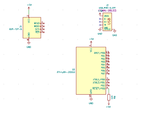
Seance 2
Projet choisis: CLavier musical
Début représentation circuit KiCad
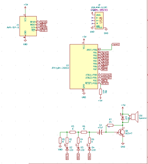
Seance 3
Création du DAC
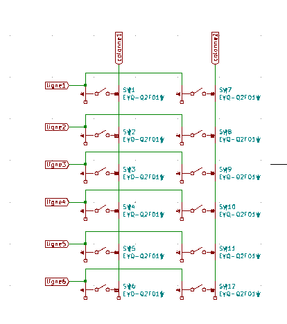
Seance 4
Présentation de notre Matrice de touches en 6x2 :
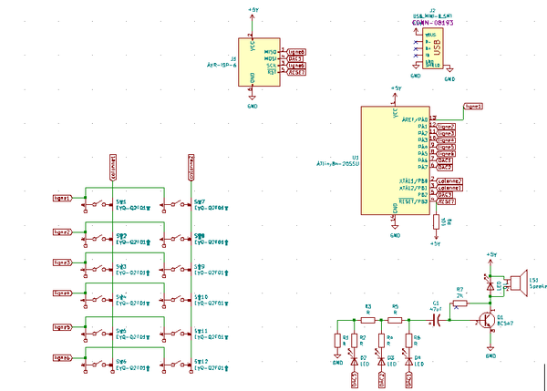
Seance 5
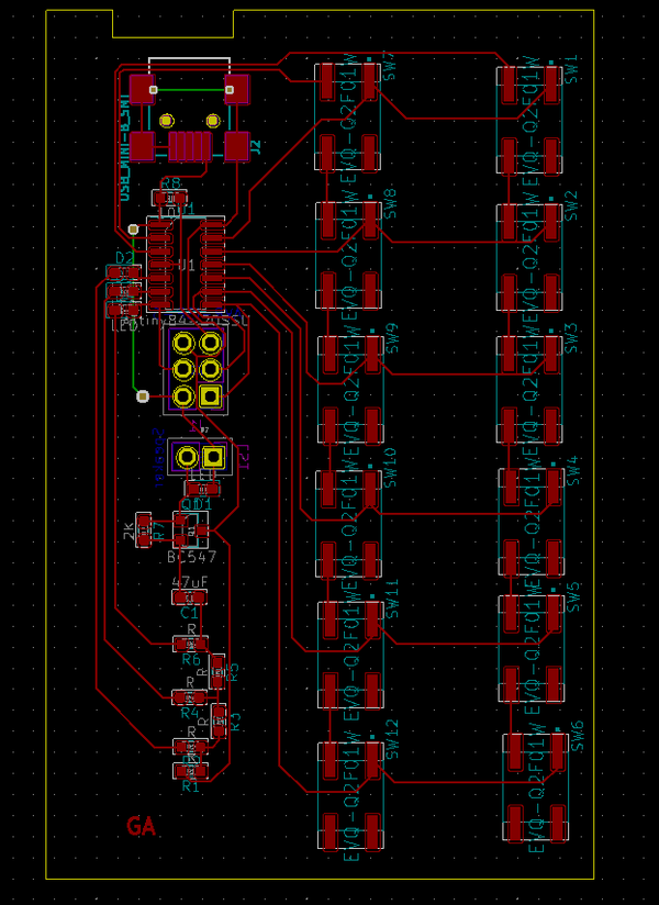
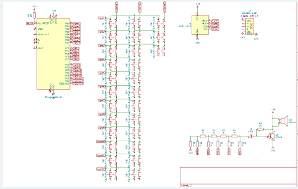
Schemas finaux de notre circuit sur Kicad et début du schéma de routage :
Seance 6
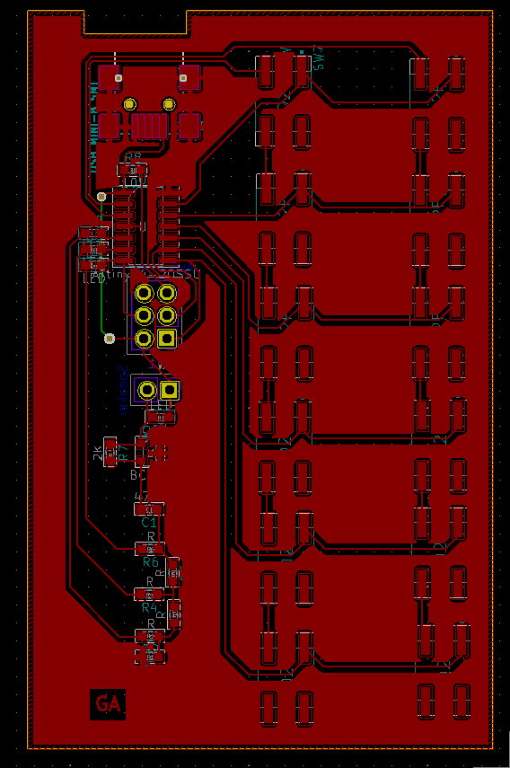
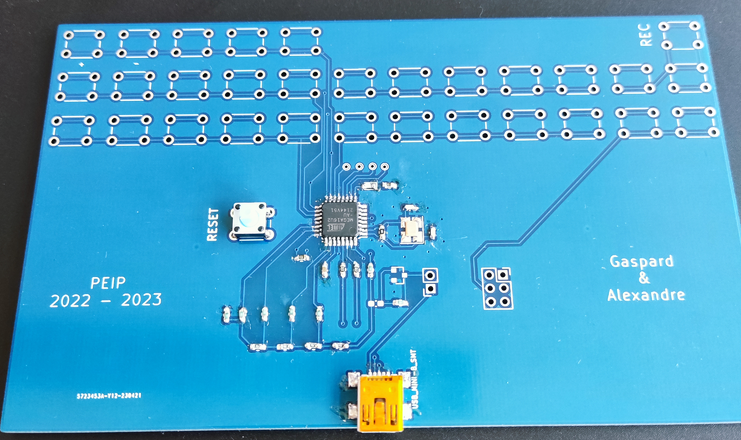
Fin du schéma de routage avec le plan de masse et découpe de la carte en fin de séance :
Seance 7
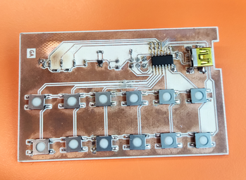
Soudage de tout les composants sur la carte
Seance 8
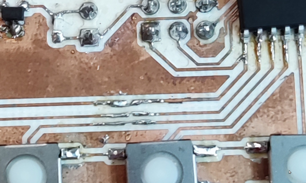
Probleme de soudure et début programmation C++ arduino
Seance 9-10-11-12
Détails des programmes les un à la suite des autres dans le ZIP.
Fichier:2022-B10 Programme.zip
Seance 13
Début projet final
Seance 14
Début soudure:
Seance 15
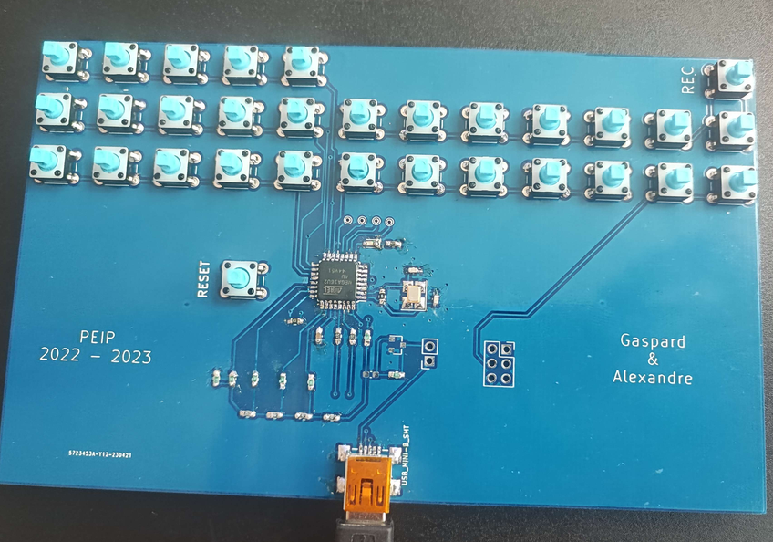
Fin de soudure sans le haut-parleur et le mosfet.
clignotement de Led test avec la carte réussi.
Début du code de la matrice 5x6 sans réussite par manque de temps, mais nous avons réussi à detecter les boutons à l'aide de la LED.
Fichier:2022-B10 ProjetFINAL.zip
